Saturday, June 18, 2011

Home dashboard V2

Since the last post, not much has happened, but I have been busy with the dashboard.


I made some changes to it, so here it is:


The left dial is the electricity consumption, and the one on the right is the gas. They go from 0 to 5, so at the moment I took the snapshot, there was a very high electricity consumption - vacuum cleaner :)
The pointer indicates the instantaneous consumption, the white number the total for the last hour, the blue number (month) is the running total for the last 30 days, as well as the cost, which is simplz the number in blue multiplied by the average cost.

It is all made using HTML5 canvas, and AJAX (I think...). On the server side, php does the job of answering the requests. The thing updates every 5 seconds, and the temperature updates every couple of minutes. The agenda fetches data from google calendar and does that only at the moment the page is loaded, so the plan is to reload the page every few hours (my agenda hardly changes...)

I now have to polish it a bit, to display properly in portable devices - it works in android 2.1 - and to lighten the load on the server...my database structure is far from ideal, and the requests take a very long time to process - 1 to 2 seconds - when most data doesn't change that fast.

Friday, May 6, 2011

Home dashboard


Here is my new dashboard for the house! this built with HTML5 and AJAX technologies (sorry if any of the terminology is incorrect, but it's hard to keep up with all these mash ups :)

This is a project that I have been thinking about for many years, and now I finally found the technologies to get it all together! And especially, the touch screens are becoming affordable, with all the tablets around, the final piece of technology will come together and I can finally stick a touch screen somewhere in the house, showing what the house is doing, and allowing control!

It became possible when I found out about RGraph, I then spent a night or two getting some graphs together, but they didn't look very slick, so I investigated, and I found a few nice dashboards, and then I almost copied one of them, this control4 energy, and after one night of iWeb, vi, php, and HTML5 coding, I got to the result above.

I think it looks really nice! I still have to make the whole interface language better and get labels closer to the fields, and that kind of usability stuff going on. This is an AJAX thing, fetches data every few seconds, and adapts the graphics and displayed information. The other pages, for gas and agenda, are not yet ready.
I am particularly proud of the pointer, which moves smoothly between the values, and keeps waving when it reaches a value, mimicking a real pointer on a car or analog meter - it's a pity I can not show it here...maybe I will do a movie...or put the html in here one day.

Hope you enjoy it!

As for the batteries of the RFID lock, they didn't last nearly as long as I had expected, so I am now powering them from a small adapter...will still consider powering them from a solar cell connected to rechargeable batteries.

Monday, May 2, 2011

RFID lock: ready! finally...

After years and years of thinking, googling and trying things out, I finally managed to finish my RFID lock!

So here is what it is: I have a door from the outside to the garden, which I use to get the bikes in the garden. There is a small slope leading to said door. I find it pretty annoying to have to go down the slope, get the keys out of the pocket, unlock the door, get in with the bike, put the bike in the shed, get the keys out again, lock the door. Especially in the rain, and in the winter, when all this implies the further step of taking the gloves out, and finding the lock hole in the dark.

For a long time I did not lock the door. I simply left it unlocked, but that always felt like a big security risk, so I started locking it. But in the back of my mind there was always the will to get it automatic. At work I have a badge which I use to get all the doors open until I reach the bike shed, and this is pretty easy to get out of the jacket pocket, even with the gloves on, so why shouldn't it be also easy to do at home.

So here is the final solution:

- a JeeNode, for wireless connectivity;
- a RFID reader module for Mifare cards, from Stronglink, an SL30
- an Abloy EL561 electronic lock (this is the expensive part of the project)

The RFID module is pretty nice, it uses I2C for communication, and can be put into sleep mode. Stronglink has a pretty good service too! quickest delivery - modules arrived in 3 days from Beijing - and when I had a problem with the power saving mode, they couldn't help me, but sent a whole new set of modules to replace mine, in case it was a hardware problem. The sleep mode problem is still there, as it doesn't quite work as expected, but I managed to get it to work in a procedure that is close to voodoo :) change something in the code and it mysteriously stops working. I wrapped it in FIMO to make a module to have on the outside, since the range on the sensor is not very big - about 4cm.

Then the Jeenode. It controls the whole thing, and when the card number is an authorised one, it closes a SSR relay, which provides 12V to the lock, thereby enabling it to be opened just by using the door handle. It also sends a radio message to the server informing which card was used. It does not yet using central authorisation, as I will need to get encryption going on for that. The Jeenode sleeps for most of the time, but wakes up every 500ms to check for a card, it then wakes up the SL30 module, checks for a card, puts the module back to sleep and sleeps again. It is now powered by 4.5V, so lets see how long before the batteries need replacement. I am hoping they will last a few months, but I will be glad if they last 1 month...

And the lock, is a pretty nice lock, which locks automatically, so the door is always locked now.it also provides a lot of signals, like cylinder used, handle down, door open, and a few more I think, but I do not yet make use of them. I want to, but that will be the next hardware iteration.

There are a lot more details, but those are for next time.

here are a few photos:

The electronics box, with the Jeenode, 12V battery for the lock, 3xAA for the controller, and the cables coming in, one from the lock, and one from the sensor outside the door.


The sensor on the outside.

Wednesday, April 27, 2011

Heating season report

The temperatures around here have been souring, although today it is back to normal, with low temperatures, and the threat of a storm approaching, but I consider the heating season officially closed!
So here is a final report of this season - 2010/2011.
Last year we started pretty early with the heating, in August, due to the birth of our little daughter, and the fact that the end of August was pretty cold already, at the end, with the last days averaging less than 15 degrees.
After that, the boiler didn't stop working, during a pretty long and cold winter, with snow for about a month, and an average December temperature of -1.1C, when it is normally 4.0C.
Last year we got a new boiler installed, a new condensing boiler, so I was very curious to be able to compare the performance of this boiler to the previous old one with pilot light. Since that one spend about 0.7m3 a day just on the pilot light, I guess I would have about 21m3 a month less than usual, which, for the 7 months of heating translates to about 150m3 less, and about 90 euro of gas (about 60 cents per m3).
But, I could not do a proper comparison, since, with the arrival of the baby our habits changed a lot. First, the overall set point was raised by 1C, from 18C to 19C; second, my wife stayed at home for most of the winter on maternity leave, so the house was warmed the whole day instead of the usual night only; third, and similar to the previous, we spend most (if not all) days/nights at home, whereas before we were going out quite often for dinner, movies, parties...

With all these to take into account, I knew that it would not be easy to compare. But anyway, here are the values, and a small analysis (sorry for the bad formatting, but couldn't figure it out...):


month Spent Predicted temperature
August 38.01 59.553 16.8
September 65.75 121.541 13.6
October 150.74 217.062 10.4
November 309.34 413.124 5.8
December 523.18 837.144 -1.1
January 415.31 537.14015 3.5
February 350.72 475.666584 4.6
March 252.13 398.224854 6.1


I did not include April although for almost half of the month the heating was still on.

This leads to a grand total of 2105.18m3 spent, against a predicted (formula based on the first year of occupancy of the house) 3059.46m3. So we spent 69% of the predicted gas consumption.
The other years this value was around 55%, so there was a large increase in our consumption, although, the comfort levels were increased and the time the house was occupied also increased significantly. Maybe it would be a nice idea to make some statistics on this, since I have all the data available.
I cannot however conclude much about the improvement, since the usage conditions have changed so dramatically. I am nevertheless convinced that if I had kept the other boiler I would have spent more than the prediction.
So overall I am quite happy with the result. Next project is still to get a PID controller going based on opentherm (maybe starting with opentherm lite) to try to get the boiler to operate in its ideal range. Now it is still on/off control, which isn't the most efficient. I do try to run the boiler efficiently by limiting the temperature of the water to 55C whenever the outside temperature allows it.

Thursday, April 14, 2011

Thermal camera

This past week I got a hold of a nice infrared camera! or thermal camera or however those things are called...

Due to unforeseen circumstances, however, I didn't have as much time to play with it, as I had foreseen, but nevertheless, I managed to take a few snapshots.
The weather has also been pretty warm (as warm as it get in Holland...) and so it was difficult to get the ideal conditions to identify heat leaks.

One of the main purposes that I was interested in it, is that we are about to change the windows, which are now steel frames - ideal cold bridges - to some high-tech aluminium profile with high performance double glass. So I wanted to snap some shots of the current windows before the new ones come in so that I can compare. I will anyway compare in the energy spending next winter. By the way, the next post will probably be the energy assessment for the past winter.

I'll get the camera again once the windows are in! and the cold sets in!

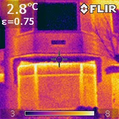
So, there is not much to say about these, but the images are nice! Here are some samples, outside the temperature was about 6C and inside 15C:


Fig. 1: The iron/steel frames, almost as cold as the outside


Fig. 2: The house outside. Upstairs we already have the nice aluminium windows, with the super glass


Fig. 3: The electricity meter - gets pretty warm in there. It would be interesting to compare it to an old fashioned one.


Fig. 4: The CNY70 doing the gas metering


Fig. 5: Heating pipes when starting to warm up, the inflow is pretty warm , as the return is still cold. That is the best case.


Fig. 6: Old cast iron radiator warming up.


Fig. 7: GU10 spots - This one is a kind of CFL


Fig. 8: GU10 spots - this one is a standard halogen.


Fig. 9: GU10 spots - this one is a 3.5W LED


Fig. 10: Just a funny picture of a plug with a switch that I use in the computer to have it completely off when not in use.

Thursday, March 31, 2011

Garage door fix

This past weekend I went to dump a lot of the stuff I collect in my garden into the garage. It opened, I dumped all the stuff, and then, when I pressed the button on the remote to close the door, it did not close. Since the door is a bit rusty, I thought that it could be stuck. It wasn't. I tried to force some the movement, it did not move. I released it from the rail, and tried to get the carrier on the rail to move, no success. My neighbor, who is a part time mechanic in the local shop, was passing by, so I asked him, he looked at it, heard it, and suggested that the gears might be worn out. Conclusion, I probably needed a new machine to open and close the door.

So, since there was nothing to loose, I decided to open it up and check if there was something that could be blocking the mechanics of the thing.

Started to take it apart, removed the cover, the motor, a 220V asynchronous I believe (winding in the stator), looked great. Here is a picture of the machine without the cover, sorry for the quality of the pictures, goes to reinforce my disbelieve in mobile phone camera quality...

Fig. 1 - Machine with the cover out, the electronics are still in on the left, where the open cover is

I then saw the electronics compartment, which could be removed by disconnecting the cable headers, so I took it out to have a look, at least out of curiosity.

Then I started looking at it, and realized that there were 2 relays, luckily transparent, which looked a bit dirty, and started to trace how the circuit worked to control the motor.

Fig. 2 - Dirty relays, you can clearly see the sooth, and although the lower one is dirtier, the malfunctioning one was the top one

Fig. 3 - Another view. The machine was tested (geprueft) in March 1990, that is 21 years ago, I hope it will last another 21!

I replugged the electronics and pressed the buttons to see what happened. When the electronics were in the "door opening" mode, all looked well, when in the "closing door" mode, there was a lot of sparking in the relay. So I knew there was a problem there.
I ran to my favorite local electronics supplier - I am lucky to have a nice little shop literally around the corner (3 minutes on the bike) where the guys have all the necessary electronics components, and know their stuff!

So I went there, and after a discussion on the behavior of the relays, which could indicate other failures, we agreed that it could only be the burned contacts. He then disassembled the board to check the pinout, and gave me two new compatible relays!

I came home, removed the old ones, soldered in the new ones, and ran to the garage to try it out.
The result, a nice working door again!

Fig. 4 - Two old relays, one of the legs is missing, so I had to do the same to the new relays.

Fig. 5 - The PCB without the relays. The power adapter is 2x9V, so the relays are being driven at 18V instead of 24V, that might also not be good for the lifetime of the relays (me complaining about something that lasted 21 years)


Fig. 6 - The new beautiful baby blue relays in place and ready for action. Now with blue relays instead of the boring beige transparent ones, the machine looks like something from this decade! maybe I should change the green LED by a blue one to really bring it into the 21st century!

I then decided to change the lock as well, since I did not know where the real key to the garage was (never used the real key since we bought the house) and if the machine would fail with the door closed, I would be in trouble. So that included a late minute run on the bike again to another nice little locksmith, which knows me by now, and always has the right supplies! Of that fix I did not take any pictures...sorry...

I was very proud of my fix, finally the electronics practice with the little projects around the house payed off! 11 euro to fix the garage opener, instead of a new expensive one! Furthermore, I now found the user manual of the machine, a Marantec 100 confort, which, since it is german and from the early 90's, it is complete with a circuit diagram, which enables me to build a new controller if I so wish, maybe one with JeeNodes and solid state relays for reliability (more on that when it comes to the RFID lock!)

Saturday, February 26, 2011

Shelves

The last post about the lamps, made me realise I have an older project, which I think was successfull, but never made it into here, so here it goes!

We have a small niche in one corner of the living room, and that had some shelves when we moved in, but they were not great, and besides, we had to completely renew the walls and so we took them out.


Original shelves (and wall color)


During the renovation process

We wanted some thick shelves, and thought of multiplex, 3 or 4 cm thick, so we went to the shop, and found a nice thick kitchen counter. We had it cut into the proper sizes, to the surprise of the operator there, that asked 3 times if we knew that that was a kitchen top.

I then routed a groove on the sides of the shelves, attached a small guide to the wall and sliped the shelves in. I am too lazy to take pictures while making it, so sorry for the lack of those.
This is the result.


That angled piece of wood is a bottle holder, also my own creation, very very simple. I might make a post about it soon! In the first picture you can see it with 3 bottles!