Wednesday, April 27, 2011

Heating season report

The temperatures around here have been souring, although today it is back to normal, with low temperatures, and the threat of a storm approaching, but I consider the heating season officially closed!
So here is a final report of this season - 2010/2011.
Last year we started pretty early with the heating, in August, due to the birth of our little daughter, and the fact that the end of August was pretty cold already, at the end, with the last days averaging less than 15 degrees.
After that, the boiler didn't stop working, during a pretty long and cold winter, with snow for about a month, and an average December temperature of -1.1C, when it is normally 4.0C.
Last year we got a new boiler installed, a new condensing boiler, so I was very curious to be able to compare the performance of this boiler to the previous old one with pilot light. Since that one spend about 0.7m3 a day just on the pilot light, I guess I would have about 21m3 a month less than usual, which, for the 7 months of heating translates to about 150m3 less, and about 90 euro of gas (about 60 cents per m3).
But, I could not do a proper comparison, since, with the arrival of the baby our habits changed a lot. First, the overall set point was raised by 1C, from 18C to 19C; second, my wife stayed at home for most of the winter on maternity leave, so the house was warmed the whole day instead of the usual night only; third, and similar to the previous, we spend most (if not all) days/nights at home, whereas before we were going out quite often for dinner, movies, parties...

With all these to take into account, I knew that it would not be easy to compare. But anyway, here are the values, and a small analysis (sorry for the bad formatting, but couldn't figure it out...):


month Spent Predicted temperature
August 38.01 59.553 16.8
September 65.75 121.541 13.6
October 150.74 217.062 10.4
November 309.34 413.124 5.8
December 523.18 837.144 -1.1
January 415.31 537.14015 3.5
February 350.72 475.666584 4.6
March 252.13 398.224854 6.1


I did not include April although for almost half of the month the heating was still on.

This leads to a grand total of 2105.18m3 spent, against a predicted (formula based on the first year of occupancy of the house) 3059.46m3. So we spent 69% of the predicted gas consumption.
The other years this value was around 55%, so there was a large increase in our consumption, although, the comfort levels were increased and the time the house was occupied also increased significantly. Maybe it would be a nice idea to make some statistics on this, since I have all the data available.
I cannot however conclude much about the improvement, since the usage conditions have changed so dramatically. I am nevertheless convinced that if I had kept the other boiler I would have spent more than the prediction.
So overall I am quite happy with the result. Next project is still to get a PID controller going based on opentherm (maybe starting with opentherm lite) to try to get the boiler to operate in its ideal range. Now it is still on/off control, which isn't the most efficient. I do try to run the boiler efficiently by limiting the temperature of the water to 55C whenever the outside temperature allows it.

Thursday, April 14, 2011

Thermal camera

This past week I got a hold of a nice infrared camera! or thermal camera or however those things are called...

Due to unforeseen circumstances, however, I didn't have as much time to play with it, as I had foreseen, but nevertheless, I managed to take a few snapshots.
The weather has also been pretty warm (as warm as it get in Holland...) and so it was difficult to get the ideal conditions to identify heat leaks.

One of the main purposes that I was interested in it, is that we are about to change the windows, which are now steel frames - ideal cold bridges - to some high-tech aluminium profile with high performance double glass. So I wanted to snap some shots of the current windows before the new ones come in so that I can compare. I will anyway compare in the energy spending next winter. By the way, the next post will probably be the energy assessment for the past winter.

I'll get the camera again once the windows are in! and the cold sets in!

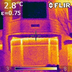
So, there is not much to say about these, but the images are nice! Here are some samples, outside the temperature was about 6C and inside 15C:


Fig. 1: The iron/steel frames, almost as cold as the outside


Fig. 2: The house outside. Upstairs we already have the nice aluminium windows, with the super glass


Fig. 3: The electricity meter - gets pretty warm in there. It would be interesting to compare it to an old fashioned one.


Fig. 4: The CNY70 doing the gas metering


Fig. 5: Heating pipes when starting to warm up, the inflow is pretty warm , as the return is still cold. That is the best case.


Fig. 6: Old cast iron radiator warming up.


Fig. 7: GU10 spots - This one is a kind of CFL


Fig. 8: GU10 spots - this one is a standard halogen.


Fig. 9: GU10 spots - this one is a 3.5W LED


Fig. 10: Just a funny picture of a plug with a switch that I use in the computer to have it completely off when not in use.

Thursday, March 31, 2011

Garage door fix

This past weekend I went to dump a lot of the stuff I collect in my garden into the garage. It opened, I dumped all the stuff, and then, when I pressed the button on the remote to close the door, it did not close. Since the door is a bit rusty, I thought that it could be stuck. It wasn't. I tried to force some the movement, it did not move. I released it from the rail, and tried to get the carrier on the rail to move, no success. My neighbor, who is a part time mechanic in the local shop, was passing by, so I asked him, he looked at it, heard it, and suggested that the gears might be worn out. Conclusion, I probably needed a new machine to open and close the door.

So, since there was nothing to loose, I decided to open it up and check if there was something that could be blocking the mechanics of the thing.

Started to take it apart, removed the cover, the motor, a 220V asynchronous I believe (winding in the stator), looked great. Here is a picture of the machine without the cover, sorry for the quality of the pictures, goes to reinforce my disbelieve in mobile phone camera quality...

Fig. 1 - Machine with the cover out, the electronics are still in on the left, where the open cover is

I then saw the electronics compartment, which could be removed by disconnecting the cable headers, so I took it out to have a look, at least out of curiosity.

Then I started looking at it, and realized that there were 2 relays, luckily transparent, which looked a bit dirty, and started to trace how the circuit worked to control the motor.

Fig. 2 - Dirty relays, you can clearly see the sooth, and although the lower one is dirtier, the malfunctioning one was the top one

Fig. 3 - Another view. The machine was tested (geprueft) in March 1990, that is 21 years ago, I hope it will last another 21!

I replugged the electronics and pressed the buttons to see what happened. When the electronics were in the "door opening" mode, all looked well, when in the "closing door" mode, there was a lot of sparking in the relay. So I knew there was a problem there.
I ran to my favorite local electronics supplier - I am lucky to have a nice little shop literally around the corner (3 minutes on the bike) where the guys have all the necessary electronics components, and know their stuff!

So I went there, and after a discussion on the behavior of the relays, which could indicate other failures, we agreed that it could only be the burned contacts. He then disassembled the board to check the pinout, and gave me two new compatible relays!

I came home, removed the old ones, soldered in the new ones, and ran to the garage to try it out.
The result, a nice working door again!

Fig. 4 - Two old relays, one of the legs is missing, so I had to do the same to the new relays.

Fig. 5 - The PCB without the relays. The power adapter is 2x9V, so the relays are being driven at 18V instead of 24V, that might also not be good for the lifetime of the relays (me complaining about something that lasted 21 years)


Fig. 6 - The new beautiful baby blue relays in place and ready for action. Now with blue relays instead of the boring beige transparent ones, the machine looks like something from this decade! maybe I should change the green LED by a blue one to really bring it into the 21st century!

I then decided to change the lock as well, since I did not know where the real key to the garage was (never used the real key since we bought the house) and if the machine would fail with the door closed, I would be in trouble. So that included a late minute run on the bike again to another nice little locksmith, which knows me by now, and always has the right supplies! Of that fix I did not take any pictures...sorry...

I was very proud of my fix, finally the electronics practice with the little projects around the house payed off! 11 euro to fix the garage opener, instead of a new expensive one! Furthermore, I now found the user manual of the machine, a Marantec 100 confort, which, since it is german and from the early 90's, it is complete with a circuit diagram, which enables me to build a new controller if I so wish, maybe one with JeeNodes and solid state relays for reliability (more on that when it comes to the RFID lock!)

Saturday, February 26, 2011

Shelves

The last post about the lamps, made me realise I have an older project, which I think was successfull, but never made it into here, so here it goes!

We have a small niche in one corner of the living room, and that had some shelves when we moved in, but they were not great, and besides, we had to completely renew the walls and so we took them out.


Original shelves (and wall color)


During the renovation process

We wanted some thick shelves, and thought of multiplex, 3 or 4 cm thick, so we went to the shop, and found a nice thick kitchen counter. We had it cut into the proper sizes, to the surprise of the operator there, that asked 3 times if we knew that that was a kitchen top.

I then routed a groove on the sides of the shelves, attached a small guide to the wall and sliped the shelves in. I am too lazy to take pictures while making it, so sorry for the lack of those.
This is the result.


That angled piece of wood is a bottle holder, also my own creation, very very simple. I might make a post about it soon! In the first picture you can see it with 3 bottles!

Tuesday, February 22, 2011

Ikea lamp

I still didn't manage to install the RFID door lock - still cold around here - so I have to do stuff inside the house!
Last year we redid the bathroom and toilets, and that included the corridor upstairs, which got a place for 3 wall lamps, instead of the hanging lamp that did not illuminate much.
So we spent lots of time looking for lamps (more than 6 months) and never found anything we liked. Even the painter, with whom we have a subscription (he should pass by every month to fix this and that), complains with us that we still did not get lamps...

To put an end to that, during a visit to Ikea, my wife had an Idea(TM - ideas from Ikea) for making a lamp...using a fruit bowl.

So we got one, and I started devising a way of installing it in the very small junction box. The final solution was a very simple 2 long M4x40 screws, on which the lamp then hangs. I installed a white lamp holder, and here is the result:


You can see the two screws on the top - I want to dip them in tippex or white paint to make them white... - there is actually just one place of all the flowers where it is possible to secure it like that.
You can also see the black hole of the junction box - that is to be covered with a piece of white rigid plastic.
What you can also see, are the 3 little rubber feet of the fruit bowl...I did not take them out as I am afraid the paint will come out...but they will have to come out sooner or later.

As for the effect when the lights are on:


It is difficult to photograph the real effect, but I can assure you that it looks very nice!
I must get some weaker lamps though...I have now 7W CFLs and with 3 of them it is a lot for such a small corridor...

Monday, December 27, 2010

End of the year

The end of the year is approaching fast! And if I look back at this blog, for this year it was pretty dead...so one of my resolutions is to make it more active, and report often on the developments here, which are slow, but plentiful.

So I will start by a project which I developed and build early in the year, and never used it, as it was a very impractical solution for the problem it meant to solve.

So, in my quest to measure things around here, and as you might remember from here, I was always curious about how much garbage we make. We separate organic garbage, glass, paper and normal garbage. And since January we have been separating plastics as well.
We then decided that we should aim at bringing the least amount of bags home, by reusing the bags we are given. But as we all know, what we can not measure we can not control, and as such I needed a way to measure how many bags we bring home.

Paper and pencil by the door would probably have done it (and resulted in a more usable solution) but I saw an opportunity to apply some electronics and build a button box, where one could press a button to indicate that a bag was brought home.

I expanded the system to be able to log all kinds of garbage, organic, paper, glass bottles, plastic garbage, bags and all other garbage.

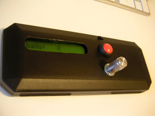
I made use of a JeeNode, of course, and used a pen box to make an enclosure. The result was pretty good I think:


(A few days later I went to California, and found a much nicer knob at a Radio Shack...no pictures though...)

Here is a picture of the guts of the machine:


I made a small board to connect everything to the JeeNode, and managed to scavenge enough pins from the JeeNode for all the necessary connections.
So here is a hint, if you need more than 8 I/O pins with your Jeenode you can use:

The IRQ pin in every port is connected to the IRQ 1 of the Arduino, which is in fact pin 3
Pins 1 and 2 of the SPI connector - connected to Arduino pins 8 and 9 (as in the JeeNode datasheet)
RX/TX in the FTDI connector - connected to pins 0 and 1 of the Arduino
SDA/SCL on the TWI connector - connected to Analog 4 and 5 of the Arduino (I think...I don't remember anymore)

and I bet you can also scavenge a few from the ISP connector. of course, by doing this you are once more away from the encapsulation that the JeeNode libraries aim to achieve...but it is always worth considering for those projects that need a lot of input/output.

In the above project, I used 6 lines to drive the LCD (in 4 bit mode), one for the switch and 2 for the knob, which uses interrupts.

The rotary encoder changes occur during the action, so I needed an interrupt to detect the action in there. More on that on a later post.

So when the power switch is turned on (no low power states) one can choose the type of garbage by turning the knob.
Upon pressing the button, it enters a "add garbage" state, where the user can add (or subtract) garbage in increments of 50 gram again by turning the knob. When a certain time elapses with no changes that amount is added to the running total and the system goes back to the choose garbage mode.

One of the options in the root menu is to send the stuff, which sends the data via wireless to the server.

The data is kept internally in the EPROM and sent over in units of 50 gram (to simplify and use integers only instead of floats), and is converted for display only.

For plastic bags and bottles the user adds units and not weight.

After all this story, I stopped using the machine after one week, after having spent hours weighing all the garbage as it went out - it is a lot of work - and my wife convinced me that I must find a better solution, or just admit that we make as much garbage as everybody else.

One simmering in the back of my head is to connect a scale directly to the system, and maybe use RFID tags to detect which garbage it is...but that is a project for the next 5 years...

I am now considering using this machine to implement my opentherm thermostat, as it has pretty much all I need, apart from the special circuitry for the physical layer.

Next post will be about the JeeNode controlled RFID lock, which, is ready, and if it wasn't for the cold outside I would have installed already!

Sunday, December 12, 2010

Weather station update!

It has been quite a while since I last posted here, it was a busy year! I became a father, and that took a lot of the time available to report - I still get quite some time to do the things, only no time to spend here reporting :) , but I hope to revive it now!

So here is an update on the weather station!

Finally, after 11 and a half months the thing died! in the coldest night of the year, after sending a packet indicating -8.1C outside at 3 in the morning...

funnily enough, the FS20 switch that turns the boiler on and off died (stopped receiving) at approximately the same time...can't explain it, it wasn't cold in the room where that one is located...

It sent 51273 messages on a set of 3AA GP branded units, which were not new when it was put outside. Since for each packet I measured the wind for 1 second, this means the JeeNode was in full power mode for a bit over 14 hours.

Anyway, I opened it, days later, and when the temperature outside was up to -1 and the batteries read about 1.9V, or about 0.6V per cell.

I wonder if the fact that the Atmega runs at 16MHz, which is out of the specs at 3.3V (let alone 1.9V), contributed to it failing at low temperature/very low voltage as well, or if it could have been pushed any harder! It is out now with a new set of batteries, since 8/12/2010, but I need to redo the anemometer, so I don't think these batteries will be out until they die!

I think this was a victory for a JeeNode in low power mode!


As for the FS20 switch, I still do not know what happened...It just would not receive, until I moved it to a different place, where reception is fine. I wonder if all the snow on the roof created some effect, which prevented it from working properly. Maybe i should try now that the snow melted. However, if that is the case, then I definitely can not leave it there, as it is precisely when it is cold and snowy outside that I need it the most!
Plans are on the making anyway for a JeeNode OpenThem controler, which should be comming soon. I already developed the control loop (PI) which determines the desired water temperature, now I just need to adjust the PI coeficients and implement the hardware, for which most components are already in the house!

I hope to report before the new year again on another project!