Thursday, November 28, 2013

Fan Controller reloaded II

So here is the continuation of the previous chapter, the saga for a nice product.

Final version:


The eagle eyed among you might notice some small changes. Nothing major.
The ones really paying attention might notice the mistakes: DS18B20 is one wire, not I2C, as is indicated (cosmetics), and the silkscreen for the 12V and the 5V regulators is inverted (cosmetics with high potential for disaster). The soldering holes for the screw connectors could also be a tiny bit bigger, but that depends on the connectors used (could be problematic, as I used some big ones).

I only noticed these mistakes after the boards arrived, luckily before soldering the regulators, so no harm done!

but, following the intense design sessions, I sent it out to be manufactured by Fritzing, and the boards arrived, a bit more than a week later! Great service is all I can say. Here they are in all their glory:


 I really think they came out amazing!

And here in the box, with some components located, not soldered yet:


And finally, in the box, with the components (attiny is missing):


In the third chapter, the completed thing, with screws, micro, lid, everything! and some considerations for improvements.

Wednesday, November 27, 2013

Fan Controller reloaded

I've been busy redoing my fan controller, and now, that I'm about to post about it, I just realize that I never presented the previous work finished, so here's a picture of the prototype:


So there it is. I especially bought those little orange and gray connectors to try out for this project.

It had been working fine for one year, but the power supply that comes with the radiator is in a DIN rail format, so I have been wanting to find a DIN rail enclosure, and make a PCB to put inside it.

I found a nice box in Conrad, and proceeded to make a shield for a JeeNode, that would fit the box. I decided to use Fritzing, to try out the manufacturing service.

1st attempt:


Great! only to realise, that the JeeNode on top of this would cover the access to the screws of the connectors. Not to mention, that the box had some mechanical constraints.

2nd attempt:

Notice that I have completely replaced the JeeNode by a Attiny of 8 pins. I decided I do not need statistics on this. So it is now a fully standalone micro-controlled controller.
notice also the mounting holes in the middle, and a big hole for a big plastic column in the box (pictures will follow). Time to print the thing and check that it fits.

3rd attempt:
Of course things didn't really fit, so I had to shift a few things around. I also decided to add some connectors to make the whole thing tidier. This is almost it! 

In the next post I'll put some pictures of the final product: beautiful boards, made in Berlin! and the assembled thing.

Wednesday, October 9, 2013

CF to SATA adapter fix

Some time ago, I bought a motherboard (ASUS AT3IONT-i) and a large disk for a project I had in mind. It was the first SATA disk I ever bought, so I was curious as to how that worked.

Plugged it all, and the disk did not work...never got recognised. Strange.

After a lot of investigation, and blaming it on the disk, I remembered I had a CF to SATA adapter lying around bought in a trip to Taipei's electronics area, so decided to give that a try, to rule out the disk.

As I plugged it in, smoke! from one of the regulators. Very strange. Upon some quick investigation, I found out that the 5V and the 12V lines on the power cable were switched, the one that came with the Motherboard. I was upset and thinking of how would they look at me in the shop if I show up with such an argument, that the lines in the cable are switched.

But it was late at night, and I wanted to get it done, so I just disassembled the cable and reassembled it properly. Unfortunately, no pictures of that. All was well afterwards! Except for the adapter that was burned.

So last time I ordered something from Conrad, I remembered that, and ordered some regulators of the same kind. Tonight I did the switch! exciting, as they are SMD components, but it went much easier than expected! Here are some photos:


Burned regulator, AMS1117-3.3


 Regulator removed


New regulator in place!

Now the adapter will go into the black hole of computer components, never to be used again! but at least it is fixed!

Monday, August 12, 2013

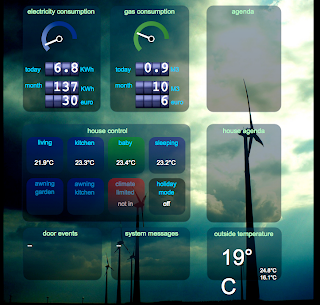
Dashboard source...finally

After a long time not having the time to take care of this, and knowing that a lot of you are out there eagerly awaiting it, I finally decided to publish it.

Then the problems started: my outdated OS doesn't interface well with github, which in turn doesn't allow for easy upload of binaries via the web interface.

So after a log of fiddling around, I managed to make a tar.gz file, with, I hope, all the necessary files to get an idea of how it works. here is the link to google docs, where I hosted it:

Dashboard: click here to download

There are a series of PHP files in there ending in "_service.php". These are the files called by the HTML5 page to update the data. They now have fixed data, and you'll have to adapt them to your own infrastructure. Also, I didn't include these service files for every functionality in the dashboard, leaving that as an exercise to you.
Also there are a few places where you'll have to insert the links to your own google agenda(s).

This is how it should look like if you dump it into a folder and access it via a suitable webserver.


Anyway, I think you probably can deal with it, and want to have it more for the design aspect then the actual infrastructure. Either way, enjoy it and have fun with it!

Having seen the recent developments in web technology with respect to sockets and stuff, I think I'll soon take my time to make this more real-time!

Let me know if it works, and if you use it, and also what you make with it!

Thursday, February 7, 2013

Fan controller

As mentioned in the previous post, I am busy with changing a radiator here in the house, and, as part of my investigations into heat distribution efficiency and space efficiency, I decided to try a radiator built in the ceiling with forced air circulation.

This will be placed in the bedroom, in the ceiling, so out of sight, apart from the ventilation grills, in the attic.

The radiator receives the heat from the standard hot water circulation system, and uses a ventilator fan to take the heat to the room.

This particular unit has a 24V DC motor, whose speed is controlled by a 0V to 10V signal, so, like I mentioned before, I built an amplifier which takes a 0 to 3.3V filtered PWM JeeNode output and multiplies it by 3, giving me a nice 0-9.9V. Here is the schematic, made using Fritzing:


It works, a basic test with a very slow sweeping output turns the motor on slowly, ramping it up to maximum speed, and back again to off.
The controller in the JeeNode will read the input and output temperatures using a pair of good old DS18B20's, and controlling the speed accordingly. I am still developing the algorithm for that (will certainly pass by some sort of PID controller).
I don't really plan on using the JeeNode radio for the control part, but will certainly be feeding back statistics later on!
The regulation of the water will be by means of the FHT8V which has now been serving in the room for the last 5 years or so!

This weekend I'll disconnect the current radiator, which takes a huge amount of space in front of the windows, and start the process of assembling the new one. We'll move to a spare room for thermal confort!!

Wednesday, January 30, 2013

PWM

For an upcoming modification to the central heating I need a controller capable of outputting a (standard?) 0 to 10V control signal.

Of course, this is a job for Arduino/Jeenode, and not for some store bough industrial controller.

Since the JeeNode works at 3.3 volts,  I set off to build an amplifier, using an LM358, wired to multiply the input by 3 times, which gives a nice and convenient range of 0 to 10V!

I am still in the process of building the circuit, but for this I needed to get the oscilloscope out.

Once I had the work on the breadboard ready I captured the following images, I thought they were nice.


I wanted to have both lines in the same shot, but my channel B is not working well, so I can only use one channel of the scope.

After I shot these, I proceeded to blow up an LM7805 (why does it have a different pinout from the LM78L12) and consequently blow up my old trusty JeeUSB version 2...I hope I can bring it back to life.

Just a short mention of what the project comprises: 0..10V controller for a 24V ventilator fan, and two Dallas 1820 measuring the temperature of the water flow (in and out). The motor will be controlled based on these.
Soon the circuits and protoboard pictures, later custom PCB's?